This is my very first Arduino project. I made a robot by using a RC Car that I found in a recycling depot. This project is structured in 3 main parts: Material List, Physical Connection and Coding.
Before we start I presume you have some basic knowledge about Arduino and C++ programming. If not I invite you to first spend some time on the official Arduino website: www.arduino.cc

Material list:
- Arduino Uno R3- L298N Motor Drive Board
- HC-SR04 Echolocation Sensor
- Tower Pro Micro servo 9g - servo motor
- red LED
- 2 x DC motors
- 9V battery
- wire jumpers: Male/Male, Male/Female, Female/Female.
- RC Car chassis and wheels
In my case DC motors were on the RC Car that I recycled so wasn't necessary to buy them. So if you find any broken RC Car toy I suggest to use that instead of buying a new one.
First step was to repair mechanical problems of the RC Car and remove unnecessary parts and I just discovered the power of the glue gun :-)

Physical connection:
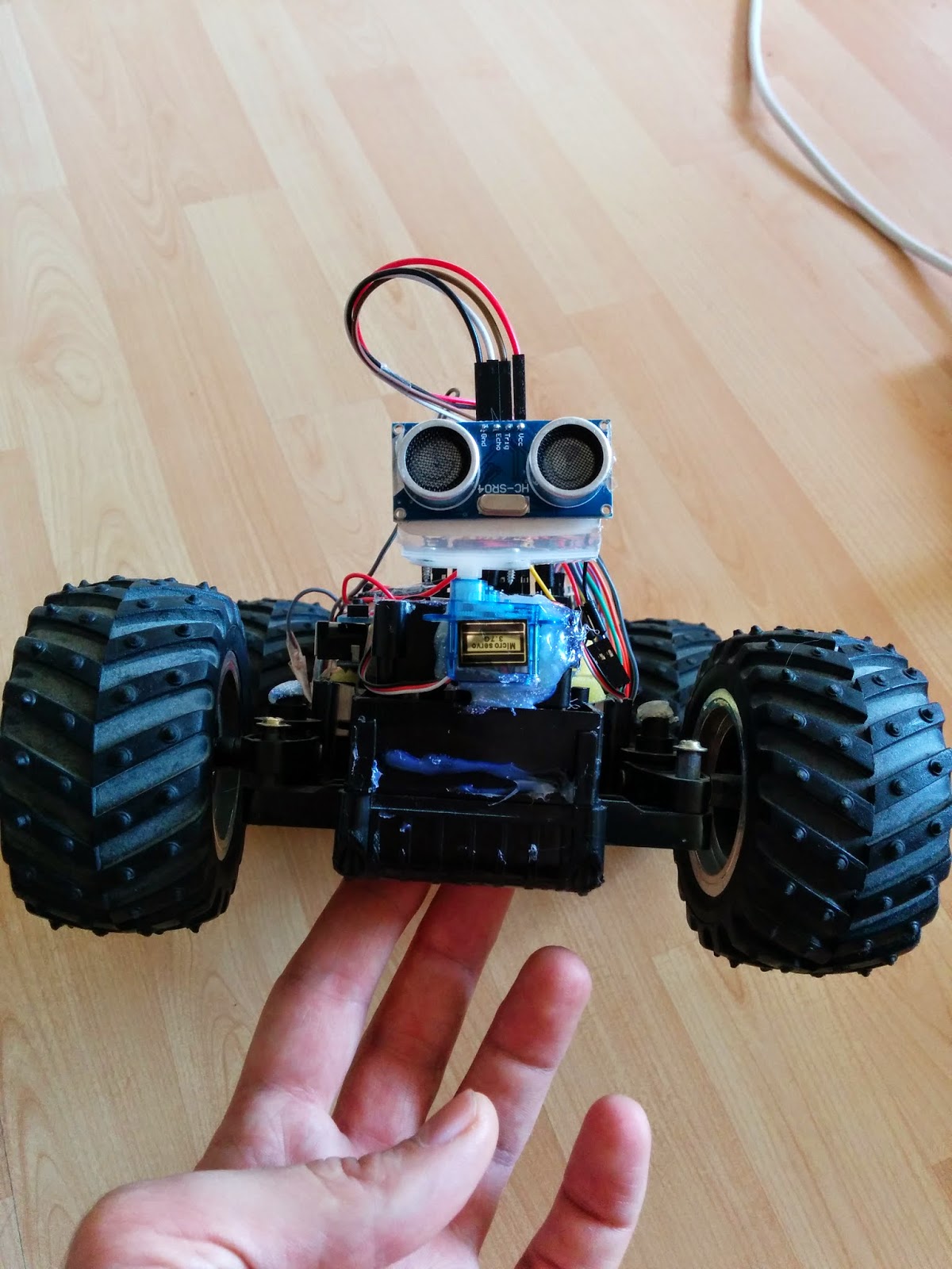
When the chassis was ready the next important step was to connect the motors, sensors and all boards to Arduino. Please follow the instructions and read the schematics. Double-check each connection and be sure that pins are connected properly.HC-SR04 Echolocation Sensor to Arduino Uno R3:
(HC-SR04: used to scan the surrounding and help the robot to find his way)
- Trig pin to I/O pin 13
- Echo pin to I/O pin 12
- VCC pin to 5V (power)
- GND pin to GND (ground)
Tower Pro Micro servo 9g to Arduino Uno R3:
(used to rotate HC-SR04 sensor)
+ (red wire) to 5V pin
- (black wire) to GND pin
signal (yellow wire) to I/O pin 9
L298N Motor Drive Board to Arduino Uno R3:
(L298N Board: used to control the DC motors of the robot)
- ENA pin to I/O pin 5
- ENB pin to I/O pin 3
- IN1 pin to I/O pin 2
- IN2 pin to I/O pin 4
- IN3 pin to I/O pin 6
- IN4 pin to I/O pin 7
- 5V pin to 5V pin
- GND pin to GND pin
Front DC Motor to L298N Motor Drive Board:
(to control direction of the robot: left/right)
+ to Motor A Output 1
- to Motor A Output 2
Rear DC Motor to L298N Motor Drive Board
(to control propulsion of the robot: forward/backward)
+ to Motor B Output 1
- to Motor B Output 2
Battery connection:
- to GND pin on Arduino
+ to VMS on L298N Board
for control of the power you can attach a button between the + wire of the battery and VMS pin on L298N Board
LED to Arduino:
(turns ON when the robot is moving backward)
+ to I/O pin 10
- to GND

Important Tips:
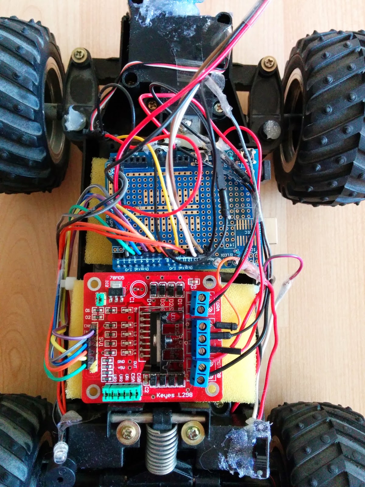
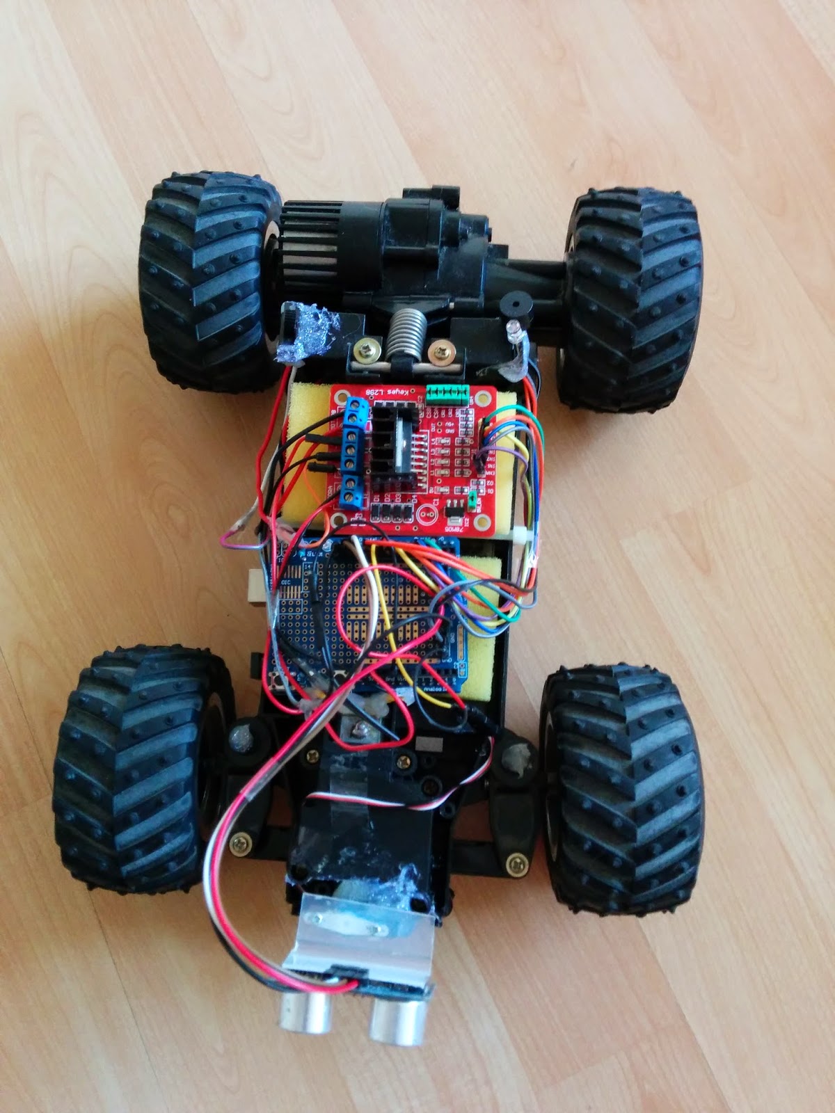
- Connect one component at the time and test it. As you can see in the photos below I've done the same.

- Since there are too many components that needs to connect to the battery I used a prototyping shield, this one multiplies the 5V pins and GND pins. On the other hand on a prototyping shield you are able to multiply any other pin from Arduino Uno R3. Don't know how a prototyping shield looks like? Check the image above.


Coding:
Important Tips:The code below may need to be adapted to your robot. Depends on the size of the robot there can occur some changes.
#include <Servo.h>
#define trig 13
#define echo 12
Servo myservo;
int servoLeft = 10; //angle of microservo rotation to scan on left
int servoForward = 45;
int servoRight = 100; //angle of microservo rotation to scan on right
int a=0;
int ena = 5;
int enb = 3;
int in1 = 2;
int in2 = 4;
int in3 = 6;
int in4 = 7;
int czas, dist1, dist2, dist3;
void setup() {
// servo pin definition
myservo.attach(9);
//buzzer
pinMode(11, OUTPUT);
//light
pinMode(10, OUTPUT);
//ultrasonic sensor
pinMode(trig, OUTPUT);
pinMode(echo, INPUT);
//motors
pinMode(ena, OUTPUT);
pinMode(enb, OUTPUT);
pinMode(in1, OUTPUT);
pinMode(in2, OUTPUT);
pinMode(in3, OUTPUT);
pinMode(in4, OUTPUT);
}
void loop() {
scanLeft();
delay(250);
scanRight();
delay(250);
scanForward();
delay(250);
if( dist3<30){
moveBackward();
digitalWrite(10, HIGH);
delay(1000);
digitalWrite(10, LOW);
moveStop();
}
if(dist2>50 && dist1<20){
turnRight();
delay(500);
moveForward();
delay(1000);
moveStop();
a=2;
}
if(dist1>50 && dist2<20){
turnLeft();
delay(500);
moveForward();
delay(1000);
moveStop();
a=3;
}
if(dist3>dist2 && dist3>dist1 && dist3>50){
if(a==2) {
lamijlocdindreapta();
}
if(a==3) {
lamijlocdinstanga();
}
moveForward();
delay(1000);
moveStop();
a=1;
}
if(dist2>dist3 && dist2>dist1 && dist2>50){
turnRight();
delay(500);
moveForward();
delay(1000);
moveStop();
a=2;
}
if(dist1>dist2 && dist1>dist3 && dist1>50){
turnLeft();
delay(500);
moveForward();
delay(1000);
moveStop();
a=3;
}
}
void scanForward(){
myservo.write(servoForward);
digitalWrite(trig, HIGH);
delay(500);
digitalWrite(trig, LOW);
czas = pulseIn(echo, HIGH);
dist3 = (czas/2)/29.1;
}
void scanRight(){
myservo.write(servoRight);
delay(50);
digitalWrite(trig, HIGH);
delay(500);
digitalWrite(trig, LOW);
czas = pulseIn(echo, HIGH);
dist2 = (czas/2)/29.1;
}
void scanLeft(){
myservo.write(servoLeft);
delay(50);
digitalWrite(trig, HIGH);
delay(500);
digitalWrite(trig, LOW);
czas = pulseIn(echo, HIGH);
dist1 = (czas/2)/29.1;
}
void moveForward(){
motorB(2, 60);
motorA(0, 0);
}
void lamijlocdindreapta(){
turnLeft();
delay(200);
}
void lamijlocdinstanga(){
turnRight();
delay(200);
}
void moveBackward(){
motorB(1, 80);
motorA(0, 0);
}
void turnLeft(){
motorA(2, 50);
motorB(0, 0);
}
void turnRight(){
motorA(1, 50);
motorB(0, 0);
}
void moveStop(){
motorA(0, 0);
motorB(0, 0);
}
void buzzerOn(){
tone(8, 440, 200);
}
void lightOn(){
digitalWrite(10, HIGH);
delay(500);
digitalWrite(10, LOW);
}
//****************** Motor A control *******************
void motorA(int mode, int percent)
{
//change the percentage range of 0 -> 100 into the PWM
//range of 0 -> 255 using the map function
int duty = map(percent, 0, 100, 0, 255);
switch(mode)
{
case 0: //disable/coast
digitalWrite(ena, LOW); //set enable low to disable A
break;
case 1: //turn clockwise
//setting IN1 high connects motor lead 1 to +voltage
digitalWrite(in1, HIGH);
//setting IN2 low connects motor lead 2 to ground
digitalWrite(in2, LOW);
//use pwm to control motor speed through enable pin
analogWrite(ena, duty);
break;
case 2: //turn counter-clockwise
//setting IN1 low connects motor lead 1 to ground
digitalWrite(in1, LOW);
//setting IN2 high connects motor lead 2 to +voltage
digitalWrite(in2, HIGH);
//use pwm to control motor speed through enable pin
analogWrite(ena, duty);
break;
case 3: //brake motor
//setting IN1 low connects motor lead 1 to ground
digitalWrite(in1, LOW);
//setting IN2 high connects motor lead 2 to ground
digitalWrite(in2, LOW);
//use pwm to control motor braking power
//through enable pin
analogWrite(ena, duty);
break;
}
}
//****************** Motor B control *******************
void motorB(int mode, int percent)
{
//change the percentage range of 0 -> 100 into the PWM
//range of 0 -> 255 using the map function
int duty = map(percent, 0, 100, 0, 255);
switch(mode)
{
case 0: //disable/coast
digitalWrite(enb, LOW); //set enable low to disable B
break;
case 1: //turn clockwise
//setting IN3 high connects motor lead 1 to +voltage
digitalWrite(in3, HIGH);
//setting IN4 low connects motor lead 2 to ground
digitalWrite(in4, LOW);
//use pwm to control motor speed through enable pin
analogWrite(enb, duty);
break;
case 2: //turn counter-clockwise
//setting IN3 low connects motor lead 1 to ground
digitalWrite(in3, LOW);
//setting IN4 high connects motor lead 2 to +voltage
digitalWrite(in4, HIGH);
//use pwm to control motor speed through enable pin
analogWrite(enb, duty);
break;
case 3: //brake motor
//setting IN3 low connects motor lead 1 to ground
digitalWrite(in3, LOW);
//setting IN4 high connects motor lead 2 to ground
digitalWrite(in4, LOW);
//use pwm to control motor braking power
//through enable pin
analogWrite(enb, duty);
break;
}
}
